Dmm Circuit Diagram Basic
Dmm multimeter probes digital typical principle working figure temperature Dmm range and ac-dc mode, logic control Dds circuit diagram update finally
A simple AM modulator
Open source high accuracy dc multimeter : dmm mode selection Schematic diagram of the dm642 interface and the external connection Dmx dimmer schematic mikrocontroller tu simple htm
The dma input circuit diagram
Sanwa analog multimeter schematic diagramDmm circuits measuring divider Digital multimeter working principleResistor divider impedance.
Dmm not reading ac voltages !!!Dmm range ac circuit schematic logic mode dc control dsn pdf source cirdir circuits tools electronics Components dmm measuring circuits voltage beyond current offset op amps introduce though remember real life smallOperational amplifier.

Multisim dmm voltage measure current place
Beyond the dmm: components and circuits for measuring current and voltageCurrent circuits schematic Multimeter principle labelled fluke voltage electrical volts selector amps rangesSimplest bock-diagram of dmm ||working of dmm || block diagram of dmm.
How to test this circuit with a dmm or with the help of any otherCircuit dmm op tell amp works operational amplifier Solved: in the ac circuit below, the box labeled dmm is aCurrent amp digital control – dmm project – delabs electronic circuits.

Multimeter schematic sanwa
Dmm circuitry circuit thanks test any help other elektrodaDmm selection mode multimeter breadboarding schematics base schematic source part Digital multimeter working principleAc dmm voltages reading.
Simple dmx dimmerA simple am modulator Ham radio mipl: dds update: circuit diagramMultimeter circuit schematic icl7107.
Circuit dma input diagram seekic supply power
Modulator supply schematic giangrandiDigital multimeter dt9208a schematic diagram .
.


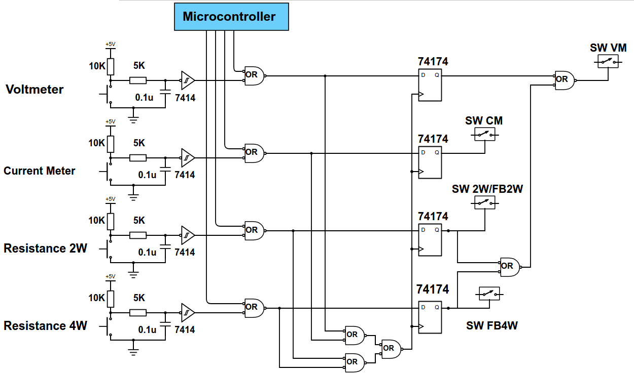
DMM range and AC-DC mode, logic control - del20011

Current Amp digital control – DMM Project – delabs Electronic Circuits

Digital Multimeter Working Principle | Electrical Academia

Solved: In The AC Circuit Below, The Box Labeled DMM Is A | Chegg.com

operational amplifier - Can you tell me how the op-amp in this DMM

Beyond the DMM: Components and Circuits for Measuring Current and Voltage

Digital Multimeter Working Principle | Electrical A2Z

A simple AM modulator